Low-Voltage Fuse Links Selection Guide
-
The purpose of using fuses is to cut off the line safely and correctly to protect discrete components or the whole line in case of circuit errors. The following are the necessary conditions to be considered when selecting fuse:
Usual Service Conditions And Installation Conditions
- Ambient temperature: -5℃ ~ +40℃
- Height above sea leavel: not more than 2000m
- Atmospheric condition humidity: the installation site's relative aire humidity does not exceed 50% while the maximum temperature +40℃, And it can allow to have higher relative humidity under lower temper . The average temperature does not exceed +25℃ while in the wettest month, and the maximum relative humidity does not exceed 90% in this month. We must take measures when there is condensation on the products which due to the changed temperature.
- Class of pollution: Third Class
- Sort of installation:Ⅲ
Design Features
-
Ambient temperature means the aire temperature directly around the fuse, and should not be understood as the room temperature. In many application cases, the fuses are at rather high temperature as they are installed with supporting devices or bases in different structures and they are closed in the distributing or controlling boxes.
Derating
-
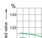
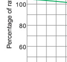
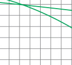
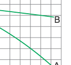
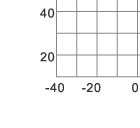
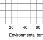
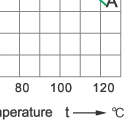
We recommend that the actual working current of a fuse should not exceed its rated current under the ambient temperature of 20℃. While selecting the fuses, environment and working conditions should be considered. Such as the variation of situation of closing, air flow, wire size(length and section) and instantaneous peak value etc. The current load capability of fuse links are tested under the ambient temperature of 20℃, However the actual load capability is affected by the ambient temperature. The higher the ambient temperature, the higher the working temperature and the shorter the service life of a fuse will be. On the other hand, the service life of a fuse can be longer when working under a lower ambient temperature.
The following is the typical curve showing the affection to the current load capability be the ambient temperature.
 |
 |
 |
 |
 |
 |
 |
 |
 |
|
Malfuction
-
Malfuction is usually a result of incomplete analysis on the design of circuit, Special attention should be given to 1) normal rated current, 3 ) Ambient temperature, 6) overload increment of factors to be considered for selection of fuses listed below. For example, frequent reasons for malfunction under normal working conditions are insufficient consideration to the start current of capacitor circuit and the ambient temperature around the fuse link.
Rated Breaking Capacity
-
Rated breaking capacity is the maximum short-circuit current allowed for the fuse link to cutout reliabley under rated voltage. The instantaneous current loaded to the fuse links is much larger than the normal working current when short-circuit occurs. The fuse links is supprted to cutout the line in an undamaged condition i.e. without bursting. The rated breaking capacity of Langir fuse is up to 120KA and the excellent current limiting characteristics reliably protect the equipment form damages by electric power.
 |
 |
 |
 |
 |
 |
|
Fuse Supporter (Fuse Base)
-
In many application cases, fuse links are installed on fuse supporters/ fuse bases. They are not to be used as switches for connection and disconnection of the load.
Factors To Be Considered For Selection Of Fuse
- Normal working current
- Working voltage
- Ambient temperature
- Overload current and cutout time
- Possible malfunction current
- Impulse current, surge current, starting current and transient value of the line
- Size and dimensions, connection methods, indicators, etc....
Threshold Values Of aM Fuses
-
Gate limit of "aM" type fuse links:
| Ip(In) | 4 | 6.3 | 8 | 10 | 12.5 | 19 |
| t Fuse ≤ | - | 60 | - | - | 0.5 | 0.10 |
| t Before arc ≥ | 60 | - | 0.5 | 0.2 | - | - |
Note:
Ip - Perspective Current
In - Rate Current of fuse link
 |
 |
 |
 |
 |
 |
